Windless Recorder
-
Build an instrument that uses capacitive touch to play musical notes,
ranging from B0 to D7.

This device takes advantage of the CapacitiveSensor and Tone libraries to create a digital instrument that can play up to 76 different notes!
No need to worry about proper breathing technique as the device relies solely on touch input.
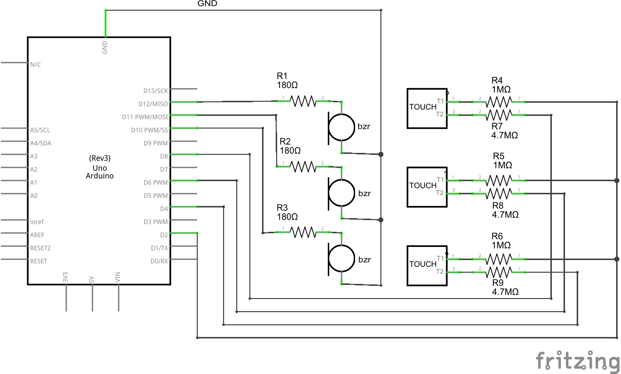
The capacitive sensor is connected between a send and receive pin. The send pin toggles between states and waits for the receive pin to change to the same state. Touching the sensor will of course effect how the receive pin changes state. The difference in time it takes for the receive pin's state to change is recorded and stored as a variable. This variable will be used to control the notes played by a buzzer.
The capacitive sensor is connected between a send and receive pin. The send pin toggles between states and waits for the receive pin to change to the same state. Touching the sensor will of course effect how the receive pin changes state. The difference in time it takes for the receive pin's state to change is recorded and stored as a variable. This variable will be used to control the notes played by a buzzer.
| Component | Quantity | Description | Where to Buy |
|---|---|---|---|
| 1M Resistor | 3 | 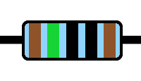 |
Canada, USA |
| 4.7M Resistor | 3 | 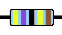 |
Canada, USA |
| 180 Ohm Resistor | 3 | 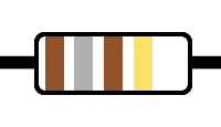 |
Canada, USA |
| Electromagnetic Buzzer | 3 | 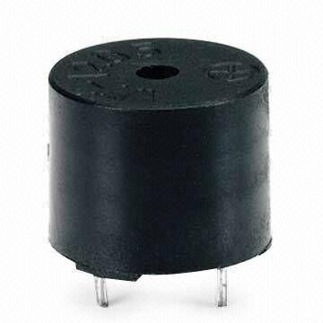 Voltage Range: 4.5 ~ 5.5V
Frequency: 2.4 kHz Voltage Range: 4.5 ~ 5.5V
Frequency: 2.4 kHz |
Canada, USA |
| Insulated Wires | ~10 | 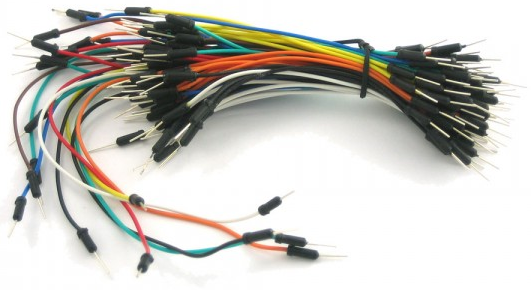 |
Kit or M/M Cables |
| Brass Thumb Tacks | 3 | 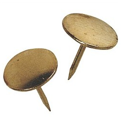
| Local Variety Store | Arduino Uno | 1 | 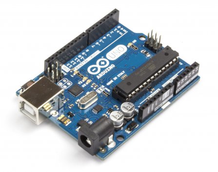 |
Board with Accessories |
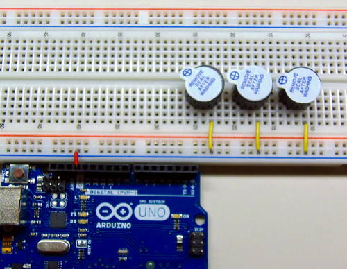
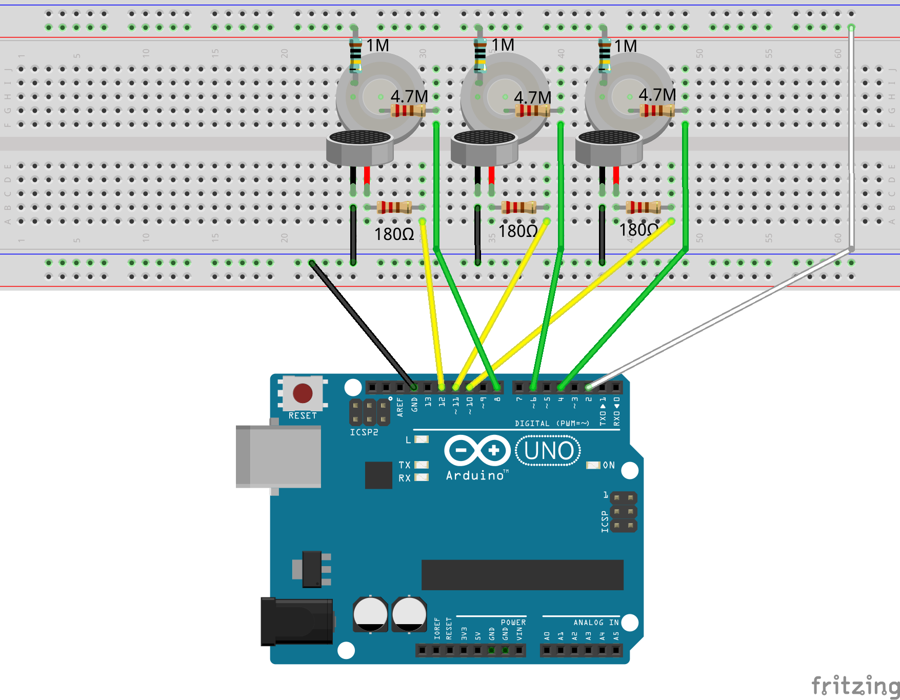
The first thing we'll do is connect the buzzers. Connect the GND pin of the Arduino board to the negative column of the breadboard.
Take three small pieces of wire and connect them from the negative column to column J.
Take each buzzer and connect their negative terminals to the rows that correspond with the wires. Placing them in column F will give you the most room to work.
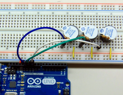
Take your three 180 Ω resistors and connected them to the rows that correspond to the positive terminals of the buzzer.
Now, connect the other ends of the resistors to pins 10, 11, and 12 via wire.
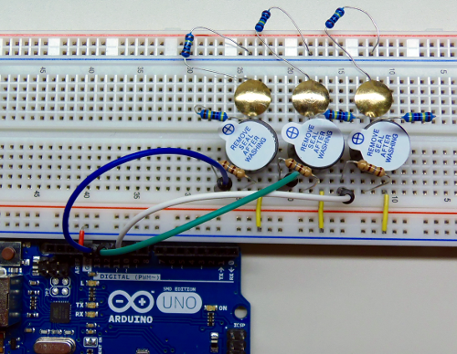
Now we'll add our capacitive sensors (thumb tacks!). The first thing we'll do is position our 4.7M resistors.
Given the radius of the thumb tacks, the best place will be at the end column, E.
Next, take the 1M resistors and place them at the opposite end of the same row. The other terminal should be placed on the adjacent negative column.
The thumb tacks should now be centred between the two resistors.
The thumb tacks should now be centred between the two resistors.
Note: the resistors may need to be cut or bent down to allow enough room to touch the sensors.
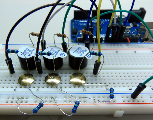
We now need to connect the send and receive pins to the capacitive sensors. Connect pins 4, 6, and 8 to the other ends of the 4.7M resistors, these are the receiving/sensing pins.
Lastly, connect pin 2 to the negative column, as to be connected to all 1M resistors.
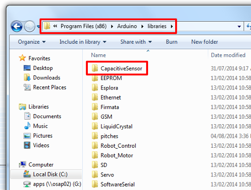
Moving onto the source code. You'll first need to download the Capacitive Sensor Library.
Save and extract the zip folder in the Arduino/libraries directory.
Here is a list of Tones
Here is a list of Tones
Source Code:
Considerations:
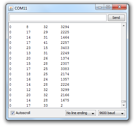
The control statements have been adjusted for my environment. Working on an ungrounded laptop meant lower readings for total1, 2, and 3. I called the notePlayer functions whenever these values were greater than 500.
If you are working on a laptop, plugging in the charger will ground the device and provide higher readings. This will vary from computer to computer, so the best thing to do is run the Serial Monitor (Tools > Serial Monitor) and customize your if-statements based on the readings.