Heads or Tails!
-
Build an electronic coin toss.

This device makes use of the built in random function that comes with the Arduino IDE.
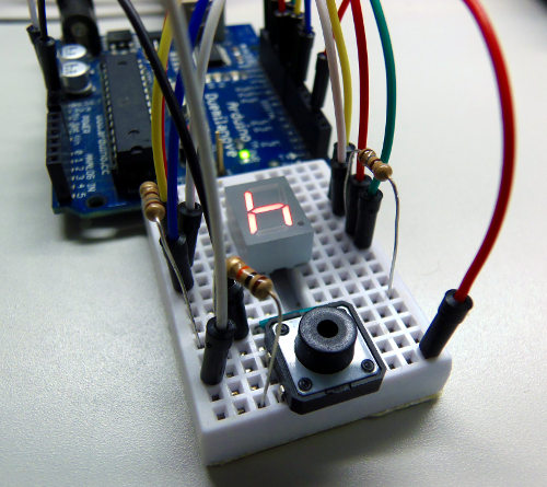
Pushing the button will random generate an "h" for heads, or a "t" for tails on the display. The segments on the display are a different style of LED, and function the same way in terms of programming. What that means is that we can set the pin associated with a segment to HIGH or LOW in order to turn it ON or OFF.
We want the chance of getting heads or tails to be 50/50, so the random function is limited to two numbers: 0 and 1. The random function takes the form random(min, max). However, the max value is not included. For instance, random(0, 10) will generate random numbers between 0 and 9. For our purposes, we’ll use random(0, 2). This generated number will be assigned to a variable called ran. If ran is 0, we'll turn on the 4 segments that form a "t". If ran is 1, we'll do the same for "h".
| 13 | 12 | 11 | 10 | 9 | 8 | 7 | 6 |
|---|---|---|---|---|---|---|---|
| Component | Quantity | Description | Where to Buy |
|---|---|---|---|
| 220 Ω Resistor | 2 |  |
Canada, USA |
| 10 kΩ Resistor | 1 | 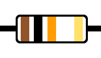 |
Canada, USA |
| 7-Segment Display | 1 | 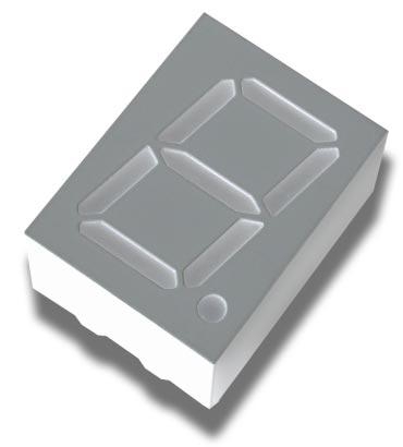 Red Red |
Canada, USA |
| Insulated Wires | ~12 | 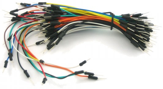 |
Kit or M/M Cables |
| Push Button | 1 | 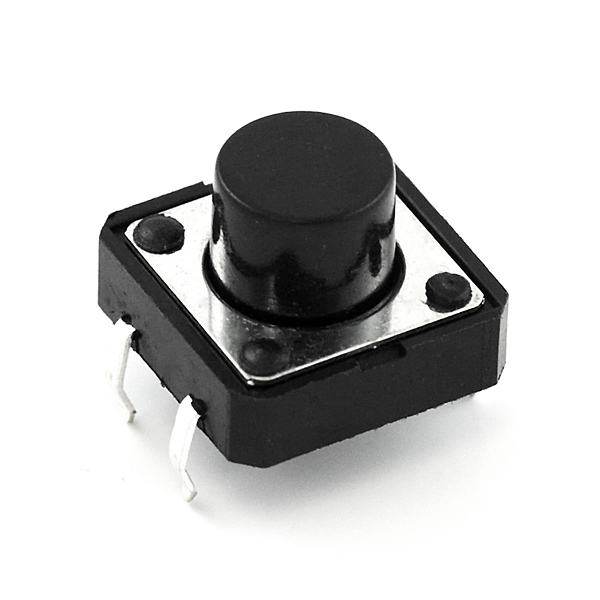
| Canada |
| Arduino Uno | 1 | 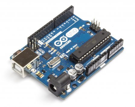 |
Board with Accessories |
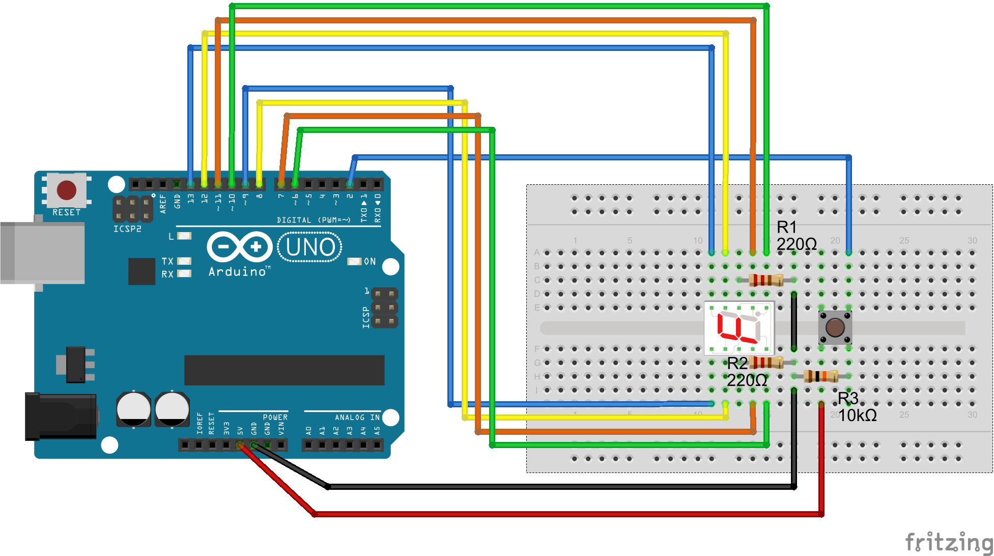
The first thing we'll do is connect our 7-segment display. Make sure the pins have their own row; it is necessary to connect the display across the middle of the breadboard.
Connect the two 220 kΩ resistors (any resistance close to this should be fine) from both center pins of the display, to a common row/node.
These two pins will eventually be connected directly to GND.
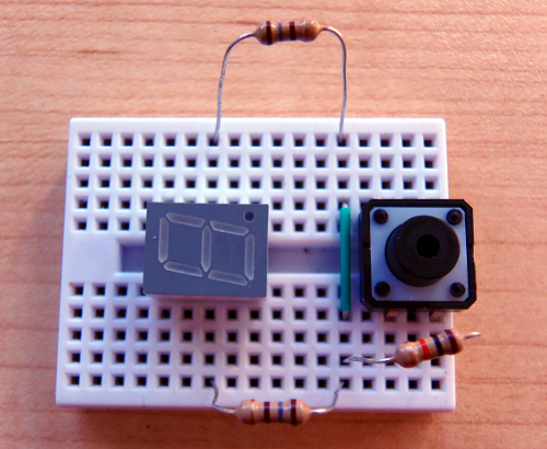
Next we'll add our button. Similar to the display, each pin on the button needs to have its own row/node, which is why it is centered on the breadboard.
Connect the 10 kΩ resistor from the bottom-right pin to the common row with the other resistors, as to be grounded as well.
Here's a guide to how buttons are typically connected to the Arduino.
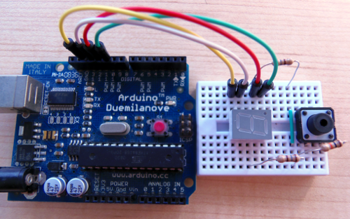
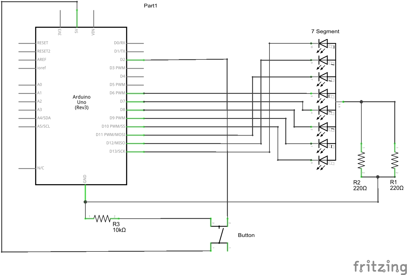
This part needs to be done correctly or else your display will seem nonsensical. Each pin will be associated with a segment on the display.
The correlations are listed in the table at the top of this tutorial.
The pins simply need to be connected in order; pin 13 connected the top-leftmost pin of the segment, to pin 10 connected to the top rightmost.
Remember that there will be a gap between them due to the resistor.
Remember that there will be a gap between them due to the resistor.
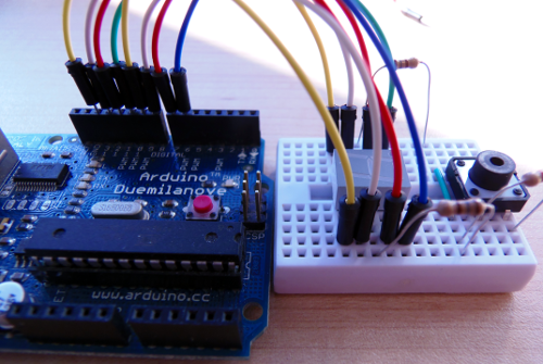
Add the remaining pins (9 to 6) in the same fashion to the bottom half of the display.
Now we'll add our power supply, ground, and sensor.
Connect a wire from pin 2 of the Arduino to the top-right pin of the button. This pin will read the state of the button, telling us whether or not it has been pressed.
Connect a wire from GND to the common row with all the resistors.
And finally, connect a wire from the 5 V pin to the bottom-left pin of the button.
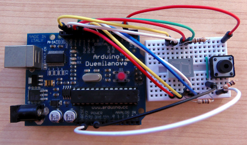
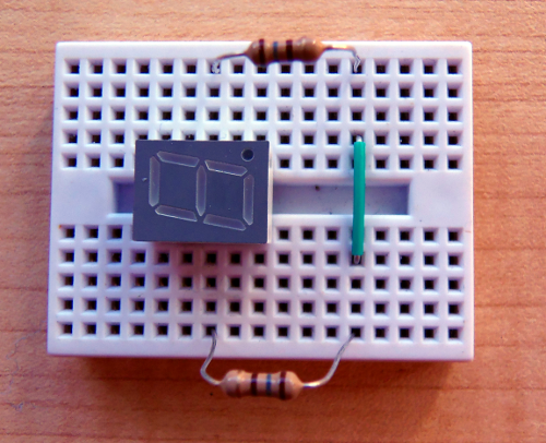
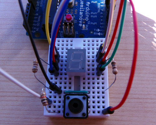
When everything is finished it should look similar to the image on the left.
Source Code:
Considerations:
<-ADD->