Interacting with the Physical World with PiFace and Adafruit Pi Cobbler
-
This tutorial will introduce you to making a Raspberry Pi interact with the physical world with the help of a PiFace or a Pi Cobbler.
It was developed by Michael Lescisin under the supervision of Dr. Qusay H. Mahmoud.
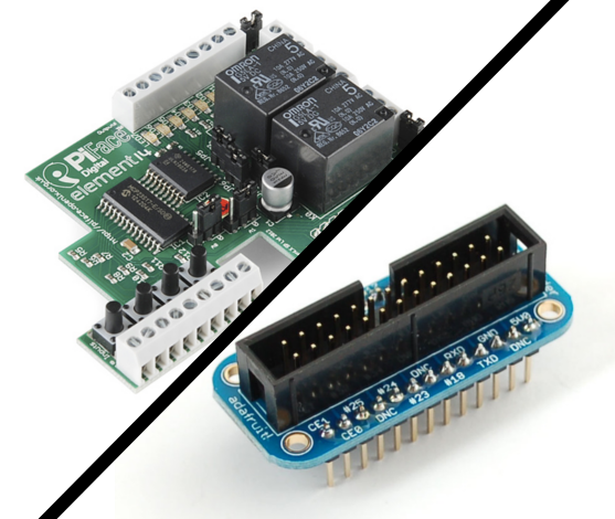
The Pi Cobbler (explored in the first half of the tutorial) acts as an adapter for the pins on the Raspberry Pi. The connection to the pins are extended by breakout cable which is then connected to the Pi Cobbler.
The pins on the Pi Cobbler fit nicely into breadboard. This gives the user easy access to features like power, GPIO, I2C and SPI.
The PiFace (explored in the second half of the tutorial) acts as an expansion for the Raspberry Pi board, creating more input and output capabilities. Its built in relays make it easy to drive motors and actuators.
The PiFace (explored in the second half of the tutorial) acts as an expansion for the Raspberry Pi board, creating more input and output capabilities. Its built in relays make it easy to drive motors and actuators.
| Component | Quantity | Description | Where to Buy |
|---|---|---|---|
| Raspberry Pi | 1 | 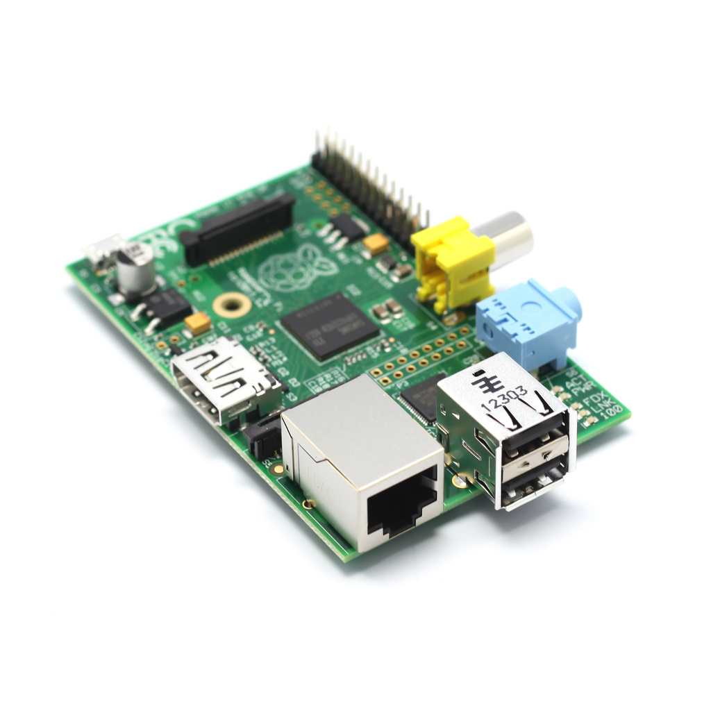 |
Canada, USA |
| SD card with Raspbian image installed | 1 |  |
Canada, USA |
| 5V USB Power Supply (a laptop or desktop will work for this) | 1 | - | - |
| USB A micro Cable | 1 |  |
Canada, USA |
| Ethernet Cable | 1 | 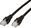 |
Canada, USA |
| Pi Cobbler (For first half of tutorial) | 1 | 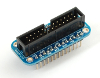 |
Adafruit |
| PiFace (For second half of tutorial) | 1 | 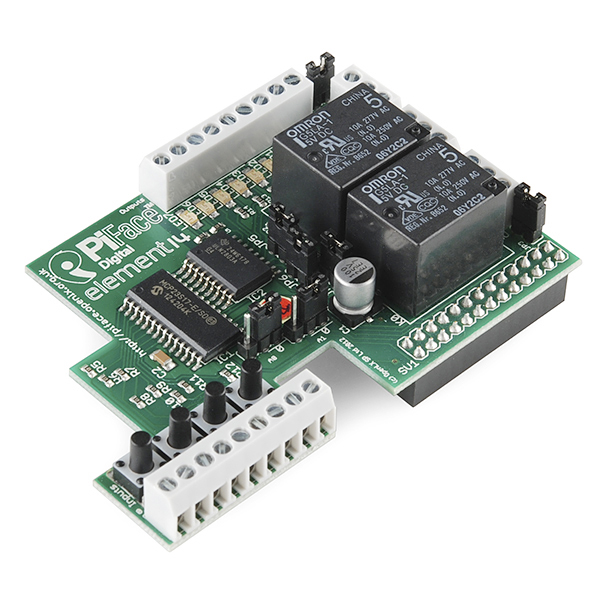 |
Sparkfun |
| Breakout Cable | 1 | 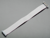 |
Adafruit |
| Red LED | 1 | 
| Canada |
| 180 Ohm Resistor | 1 | 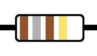 |
Canada, USA |
| Insulated Wires | ~2 |  |
Kit or M/M Cables |
Setting it up (Pi Cobbler):
-
1. Ensure that you have successfully completed the previous tutorial so that you can log in to the Raspberry Pi over SSH as well as connect to the Internet from the Raspberry Pi.
2. Turn off and unplug the Raspberry Pi.
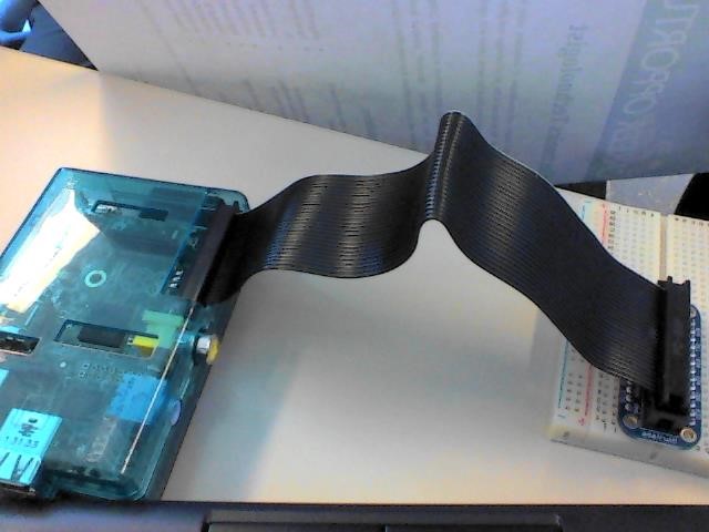
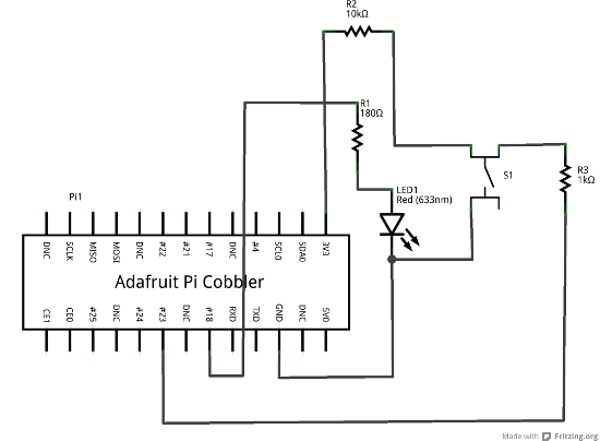
3. Insert the Pi Cobbler into a solderless breadboard and connect it to the Raspberry Pi with the 26-pin ribbon cable. Do this so that the ribbon cable faces away from the Raspberry Pi.
-
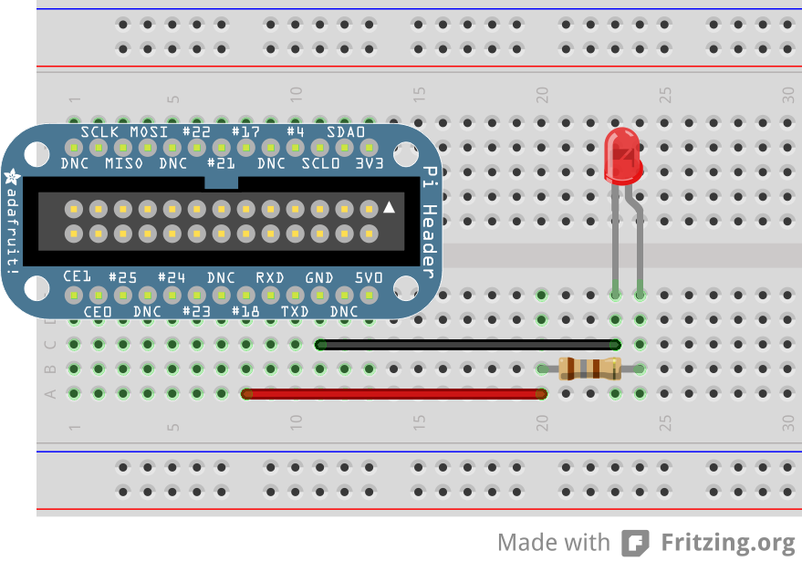
4. Connect a 180O (brown, grey, brown, gold) resistor between pin "#18" and a breadboard pin that is not connected to the Pi cobbler.
5. Connect the positive (long) leg of an LED so that it is connected to the end of the resistor on the opposite side of the Raspberry Pi.
6. Connect the negative (short) leg of the LED to "GND" on the Pi cobbler.
7. The solderless breadboard should look like this.
-
8. Turn on the Raspberry Pi, connect it to your laptop with Ethernet, and open a PuTTY SSH connection to it.
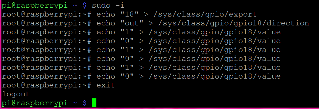
9. The following commands need to be run as root. To do so type
sudo -i
10. In order to control this pin, we must first "export" it. To export pin 18, run the following command:
echo "18" > /sys/class/gpio/export
11. We must now set the direction of pin 18, run the command:
echo "out" > /sys/class/gpio/gpio18/direction to make GPIO pin 18 an output.
12. Finally to turn on pin 18 (and thus turn on the LED) run the following command:
echo "1" > /sys/class/gpio/gpio18/value
13. The led should now be on.
14. To turn off the LED run the following command:
echo "0" > /sys/class/gpio/gpio18/value
15. The led should now be off.
-
16. To exit the root terminal prompt, run the command: exit.
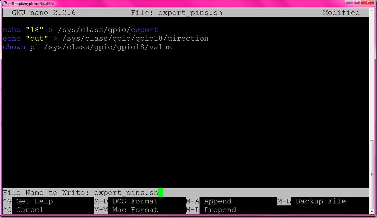
17. We now are going to set up GPIO pin 18 so that it is accessible by a program running as the normal "pi" user.
18. Change to the directory /usr/local/bin/ by running the command
cd /usr/local/bin.
19. Open the nano text editor as root by running
sudo nano.
20. Add the following lines:
echo "18" > /sys/class/gpio/export

echo "out" > /sys/class/gpio/gpio18/direction

chown pi /sys/class/gpio/gpio18/value
21. Press Ctrl+O to save the file, and name it export_pins.sh. Press Ctrl+X to exit.
-
22. Make the file executable by running the command
sudo chmod +x export_pins.sh
23. Now, make this file run at boot time by adding it to root's crontab. Run the command
sudo crontab - e and add the line @reboot /usr/local/bin/export_pins.sh to the bottom of the file.
-
24. Press Ctrl+O to save the file, and then Ctrl+X to exit.
25. Run
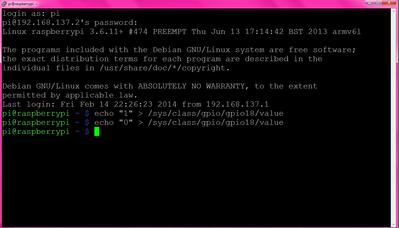
sudo reboot, and then reconnect to the Pi. You are now ready to write to GPIO pin 18 as a non-root user.
26. As the Pi user, run the command
echo "1" > /sys/class/gpio/gpio18/value (the LED should now be on)
27. As the Pi user, run the command
echo "0" > /sys/class/gpio/gpio18/value (the LED should now be off)
-
28. We can now control the LED in a C++ program just by writing to /sys/class/gpio/gpio18/value as if it were any other file.
29. Take a look at the example code to the left, it blinks an LED. Notice that flush() must be called so that the data is immediately written, and not buffered. Notice how sleep() is called to affect the blinking rate of the LED.
-
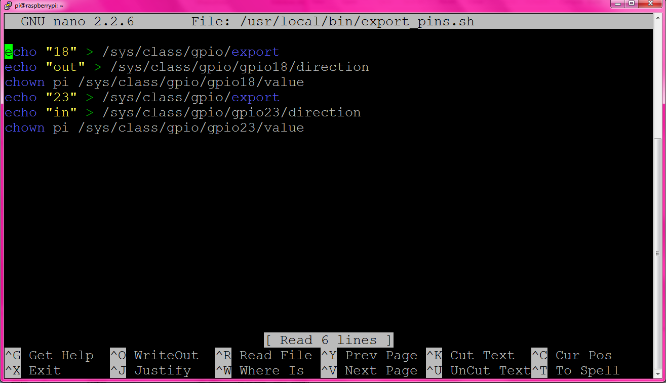
30. We will now continue this example with reading the state of a switch from GPIO input 23.
31. Modify the export_pins.sh file by running the command
sudo nano /usr/local/bin/export_pins.sh. Add the following lines:
echo "23" > /sys/class/gpio/export

echo "in" > /sys/class/gpio/gpio23/direction

chown pi /sys/class/gpio/gpio23/value
32. Press Ctrl+O to save the file, then Ctrl+X to exit.
-
33. Now run
sudo reboot and reconnect to the Pi.
34. We will now build a circuit that will allow a switch to communicate with the Raspberry Pi. Build it by following the given schematic shown on the left. Notice how nothing needs to be removed from the previous circuit.
35. Run the command
cat /sys/class/gpio/gpio23/value without pressing the switch. 1 should be printed.
36. Now press and hold the button and run the above command again. 0 should be printed.
37. Reading the state of the pin in a C++ program is like reading any other file in C++. Just remember that the file can not be repeatedly read; you must open it, read the state, then close it for all times you want to poll for input.
-
38. Here is an example of a program that reads the state of a push button switch and turns an LED on if the switch is up and off if the switch is down.
39. You are now able to use the GPIO pins on the Raspberry Pi, for controlling outputs and receiving inputs.
Setting it up (PiFace)
Source: https://www.sparkfun.com/products/11772
-
1. Remove any previous GPIO configurations. If you followed the above tutorial, run
sudo crontab -e and comment out (by adding a '#' to the front) the line @reboot /usr/local/bin/export_pins.sh.
2. Press Ctrl+O to save, and Ctrl+X to quit nano.
3. Run
sudo reboot and reconnect to the Raspberry Pi.
4. Create a new directory called piface by running the command
mkdir piface.
5. Switch into that directory by running the command
cd piface.
6. Make sure your Raspberry Pi has Internet access.
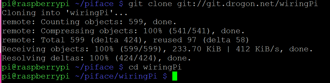
7. Now, download wiringPi by running
git clone git://git.drogon.net/wiringPi
-
8. Switch into the wiringPi directory by running
cd wiringPi.
9. Build wiringPi by running the command
./build
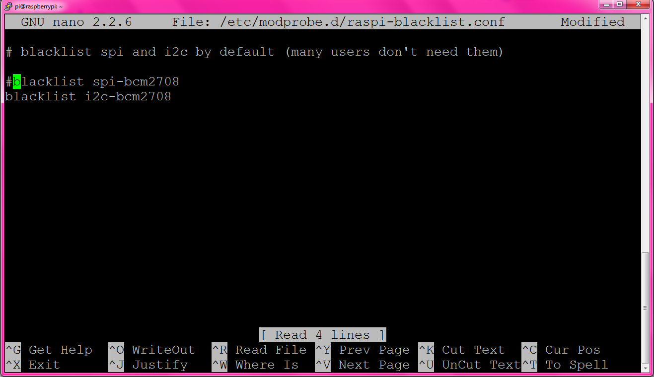
10. Run the command
sudo nano /etc/modprobe.d/raspi-blacklist.conf and comment out the line blacklist spi-bcm2708. Press Ctrl+O to save, and then Ctrl+X to quit nano.
-
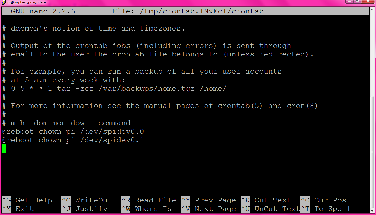
11. Run the command
sudo crontab -e and add the lines @reboot chown pi /dev/spidev0.0 and @reboot chown pi /dev/spidev0.1
12. Turn off the Pi by running
sudo halt, then connect the PiFace,
13. Restart the Raspberry Pi and login with PuTTY.
-
14. When writing a program that will use the PiFace we must first include
-
15. Compile your program with the command
g++ piface_example.cpp -l:/usr/local/lib/libwiringPi.so -l:/usr/local/lib/libwiringPiDev.so -o example
16. To the left is an example program that uses both a PiFace switch (input) and a PiFace LED (output).
17. You are now able to interface with the physical world using the PiFace.